Magnetron Wiring Diagram
Magnetic contactor wiring diagram pdf. In this case as shown, we can have rotating magneto with fixed coil or rotating coil with fixed magneto for producing and supplying current to the primary, the remaining arrangement is the same as that of a battery ignition.
Briggs And Stratton Wiring Diagram Wiring Diagram
Power must be disconnected before servicing this appliance wiring diagram warning :

Magnetron wiring diagram. It reveals the elements of the circuit as streamlined forms and also the power and also signal connections between the gadgets. It shows how the electrical wires are interconnected and can also show where and how components are connected to the system. Magnetic contactor circuit diagram luxury thermal overload relay.
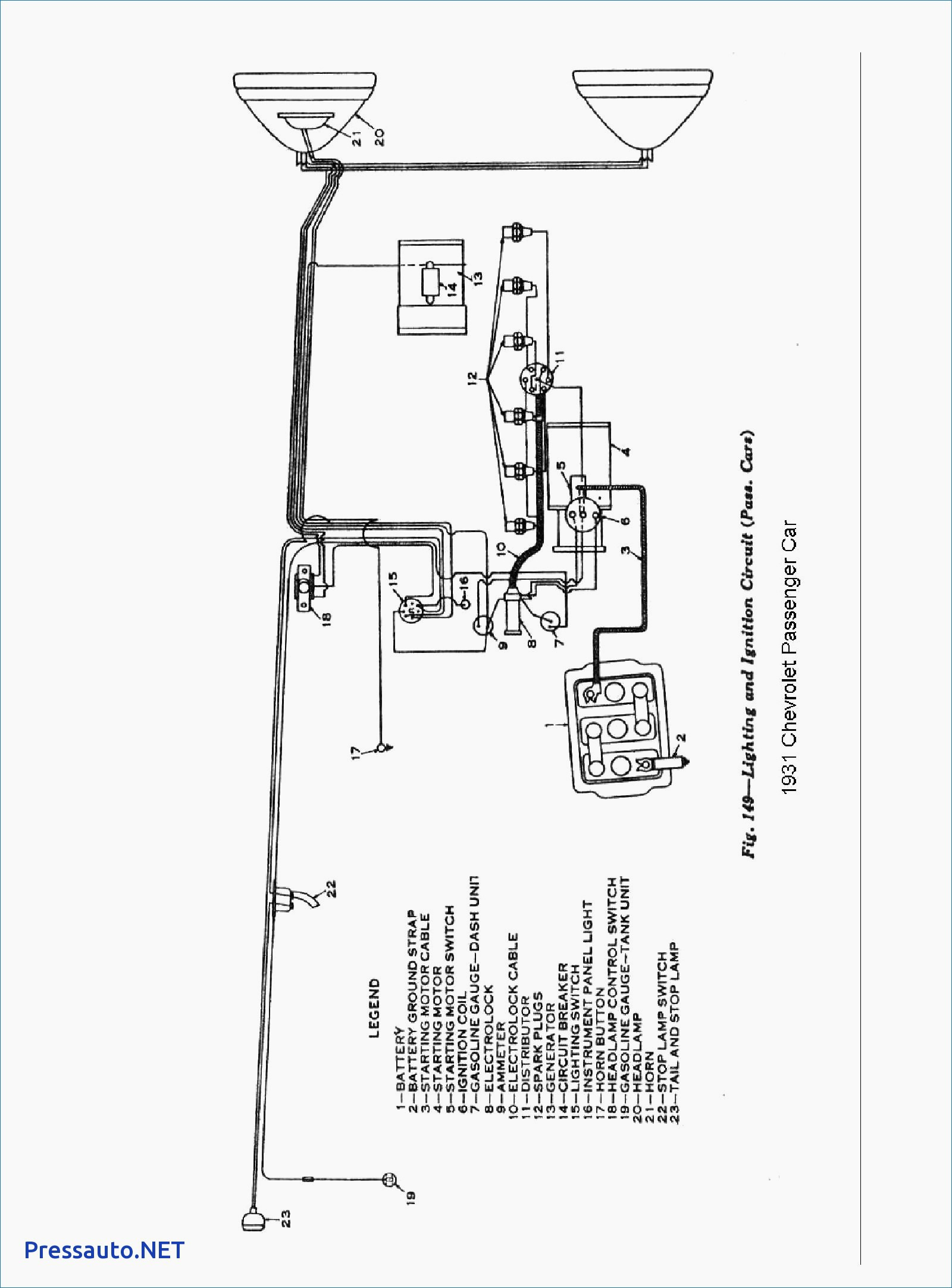
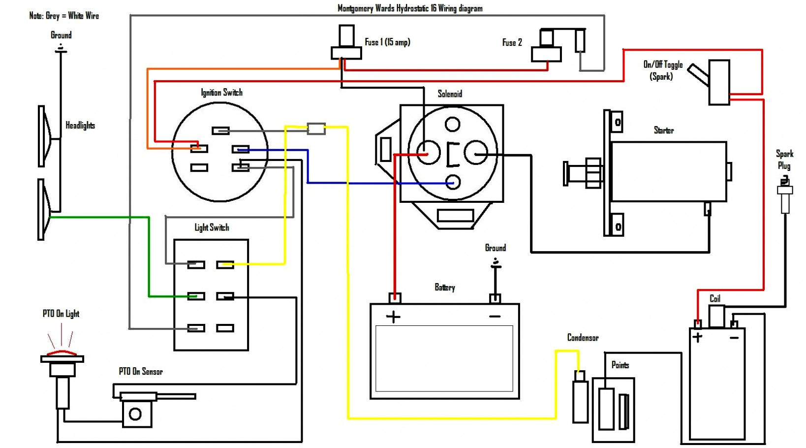
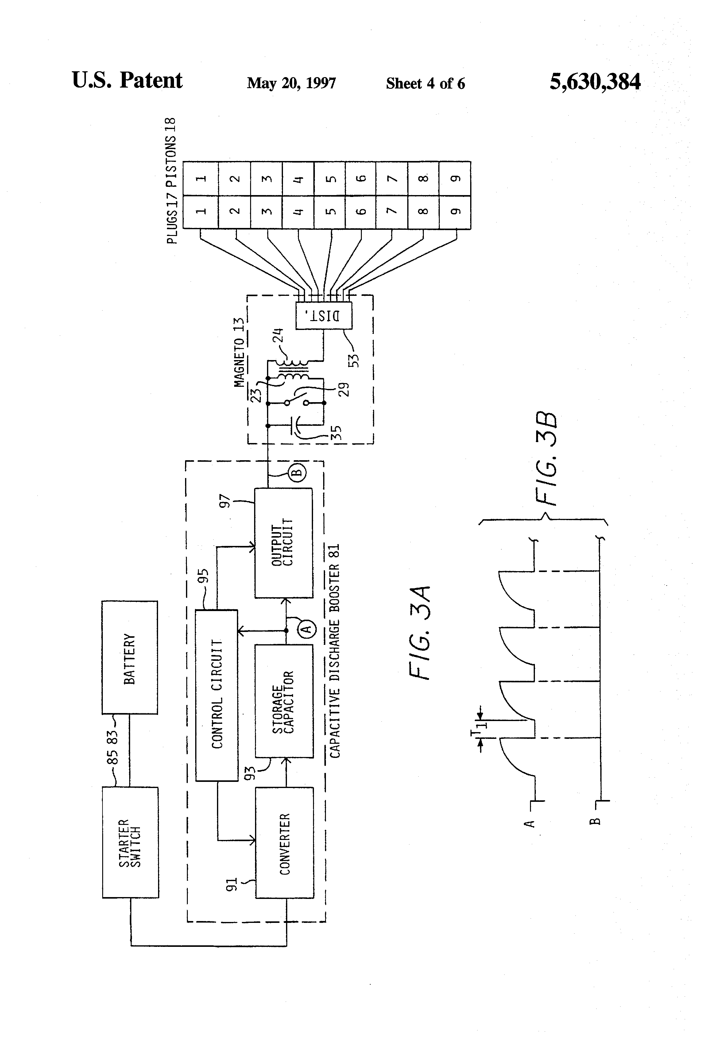
Sample basic wiring diagram for small engines using magneto ignition with points here is a basic wiring diagram showing how to wire a vintage small engine that uses a magneto ignition system with points for the timing. 1 trick that i actually use is to print exactly the same wiring plan. Print the wiring diagram off in addition to use highlighters in order to trace the signal.
Air conditioner contactor wiring diagram inspirationa wiring diagram. It contains guidelines and diagrams for various types of wiring techniques as well as other products like lights, home windows, and so on. When you make use of your finger or follow the circuit together with your eyes, it may be easy to mistrace the circuit.
Magnetic starter wiring diagrams for 30 amp 110220 volt coils disconnect all power to the unit before installing or repairing. 3 phase magnetic contactor wiring diagram. Whereas all stored energy in a conventional is confined to the vane resonators, in a coaxial magnetron approximately
Collection of contactor wiring diagram pdf. In this video discussed about microwave oven specifications, interlocks, wiring diagram, troubleshooting w.r.t various problems. Shut off the main power.
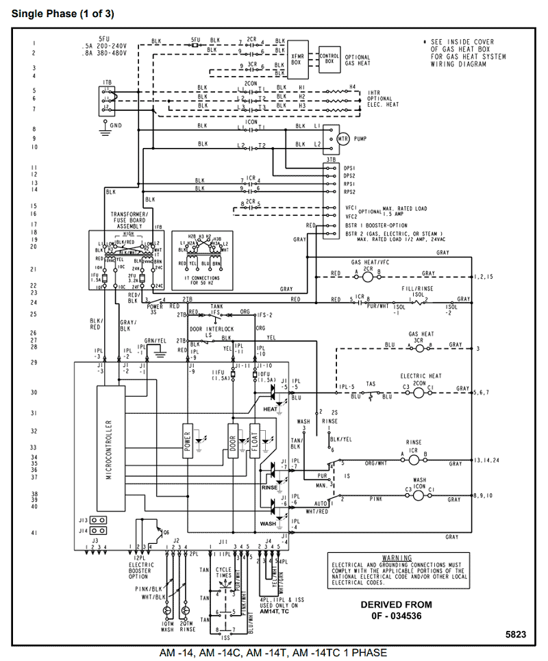
If you have a 120v coil instead of running a line from coil overload l2 you must run coil overload neutral. Orange red blue blue black t1 l1 l1 l2 l3 l2 l3 x2 t2 t3 to 208230v supply coil 3421 3 to stp see diagram g. For servicing replacement use 16ga,105 c thermoplastic covered wire except for high voltage leads or as noted on special leads.
This means lower cathode emission density, lower life and higher reliability. Door is open made in china model no. To read a wiring diagram, first you must know what fundamental elements are included inside a wiring diagram, and which pictorial symbols are used to represent them.
Model c contactor a three phase starter b single phase starter type. A wiring diagram gives the necessary information for actually wiring up a group of control devices or for. Line diagrams show circuits of the operation of the controller.
The internal parts of the mi. The following common wiring diagrams are available: Three phase contactor wiring diagram electrical info pics first of all wire the cb circuit breaker but do not switch on.
Magnetic contactor wiring diagram from lh5.googleusercontent.com. Up to 6% cash back schematic diagram warning : This will conver t the ac to dc.
Remove red wire connecting x2 to l2. Reduced rf fields in the anode: The block diagram of the power supply is as shown fig 3.1.
Installation instructions e series magnetic lock outswing electrical instructions: Easy online ordering for the ones who get it done along with 24/7 customer service, free […] Samples of engines like this include the kohler k141, k161, k181, and some k241 engines.
Rewire red wires at coil. The wire we actually use for the connection is the green one that extends past that blue wire and the power. Magnetic contactor wiring diagram pdf.
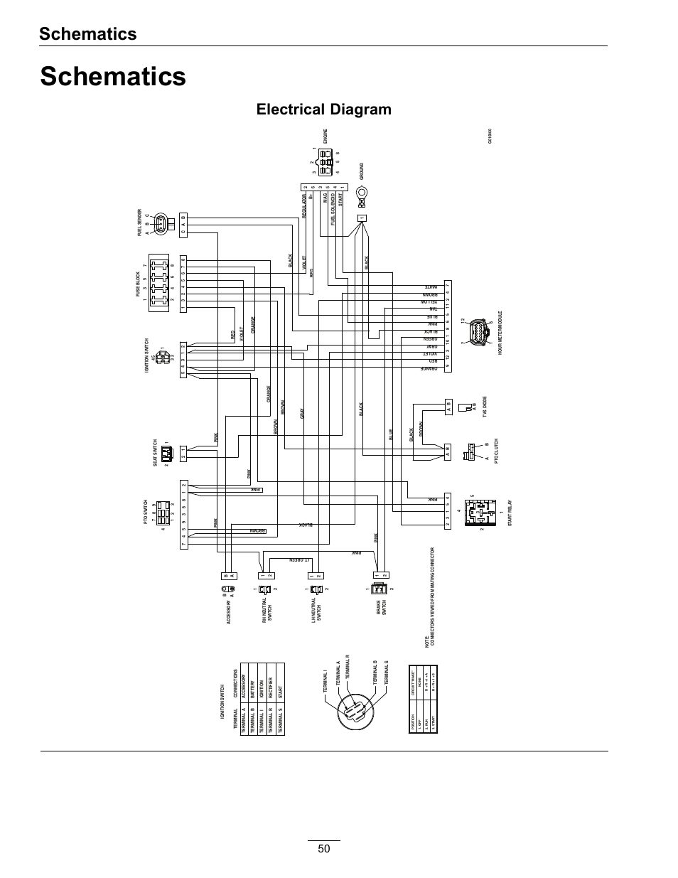
Contactor wiring diagram for 3 phase motor with overload magnetic contactor wiring diagram pdf electrical wiring magnetic contactor diagram c3rt1034 contactor relay circuit breaker wiring diagram magnetic 3 phase contactor wiring diagram pdf electrical circuit schematic diagram of a multimagnetic circuit pma 1 pole 2 working. Wiring diagram for motor starter 3 phase controller a wiring diagram is a simplified traditional photographic depiction of an electrical circuit. Figure 1 is a typical wiring diagram for a three phase magnetic motor starter.
Wiring diagram consists of several in depth illustrations that display the connection of various things. Manual and magnetic across the line starters may be applied. Air conditioner contactor wiring diagram inspirationa wiring diagram.
A wiring diagram or schematic is a visual representation of the connections and layout of an electrical system. The common elements in a very wiring diagram are ground, energy, wire and connection, output devices, switches, resistors, logic gate, lights, etc. With this sort of an illustrative guidebook, you are going to have the ability to troubleshoot, avoid, and total your assignments without difficulty.
The following reference sections provide installation documents and wiring diagram schematics for maglocks. Coil above is wired for 230 v to pump motor 120. Wired in series power supply for fail safe strikes and magnetic locks should be dc.
If this is not available you may use an ac power source and wire inline a "full wave bridge" rectifier.
Wiring Diagram
Wiring Diagram
Briggs And Stratton Wiring Diagram Cadician's Blog
Patent EP0822735A2 Microwave oven wiring Google Patents

Slick Wiring Diagram Wiring Diagram Schemas

Wiring Diagram

Wiring Diagram

Slick Wiring Diagram Wiring Diagram Schemas

Slick Wiring Diagram Wiring Diagram Schemas
Wiring Diagram

Wiring Schematic in 2021 Electric radiator fan, Motorcycle wiring, Trailer wiring diagram
Slick Wiring Diagram

Wiring Diagram

Moto Guzzi Super Alce Restoration and Ignition Timing
Wiring Diagram

Wiring Diagram

Wiring Diagram
Mallory Wiring Diagram For Your Needs


Ignition System Wiring Diagram Best Cdi Capacitor Discharge Ignition Circuit Demo