1734 Vhsc24 Wiring Diagram
Counter and 4 compare windows with an input voltage of 24 volts dc. We carry the entire point i/o 1734 series.
1734 Vhsc24 Wiring Diagram arjunariyanti
(ladder) the window comparisons part (grt and les) and other part of the process.
1734 vhsc24 wiring diagram. Follow these guidelines when you handle this equipment. Expansion power supplies may be used to provide additional pointbus backplane current. Our partnernetwork™ offers complementary product solutions for 1734 point i/o modules and 1734 point i/o add on profiles through the encompass product reference program.
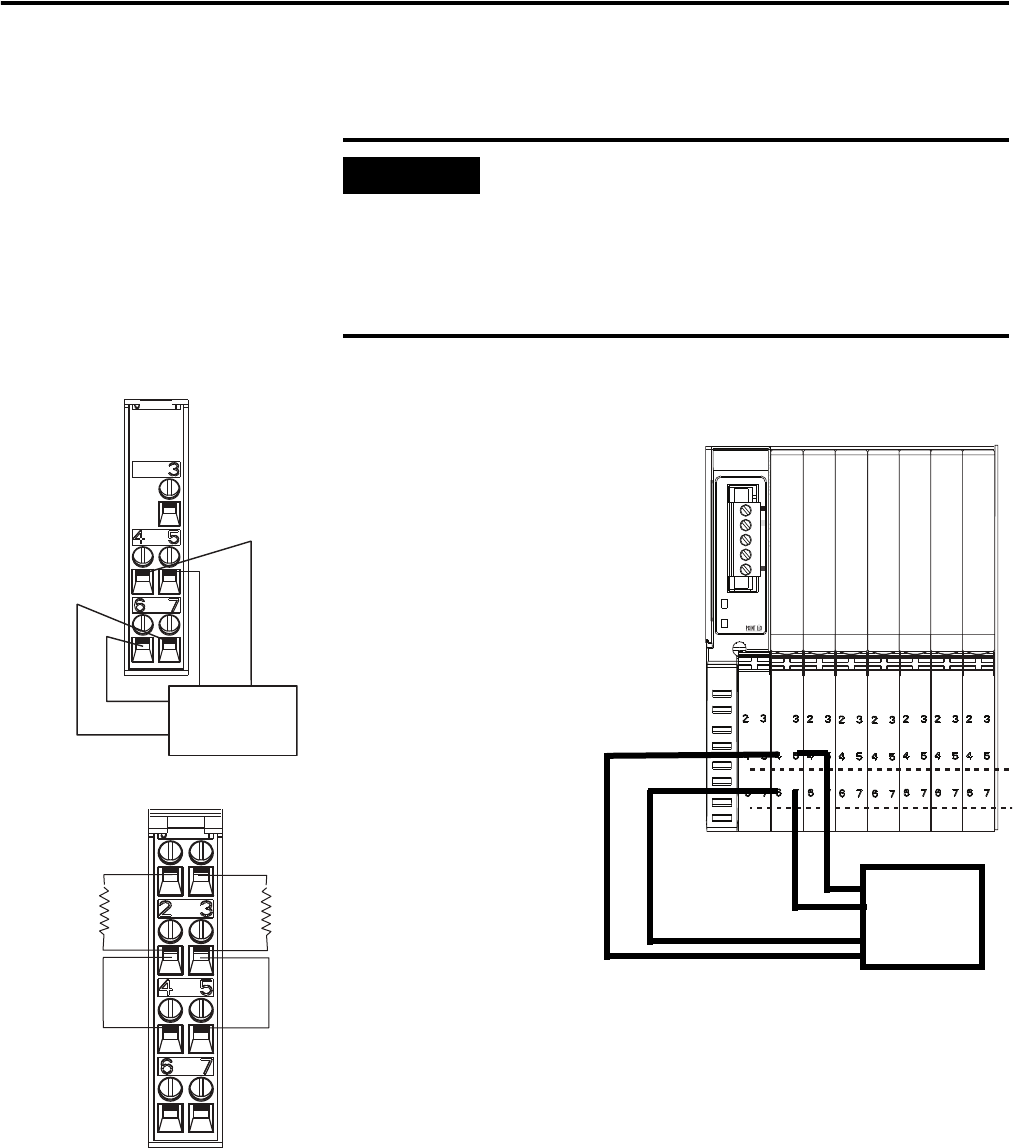
6.1 ma @ 15v dc, 10.2 ma @ 24v dc. Wiring the sensor to point io. • module 2 provides screw terminals necessary to access chassis ground (chas gnd) and common (c).
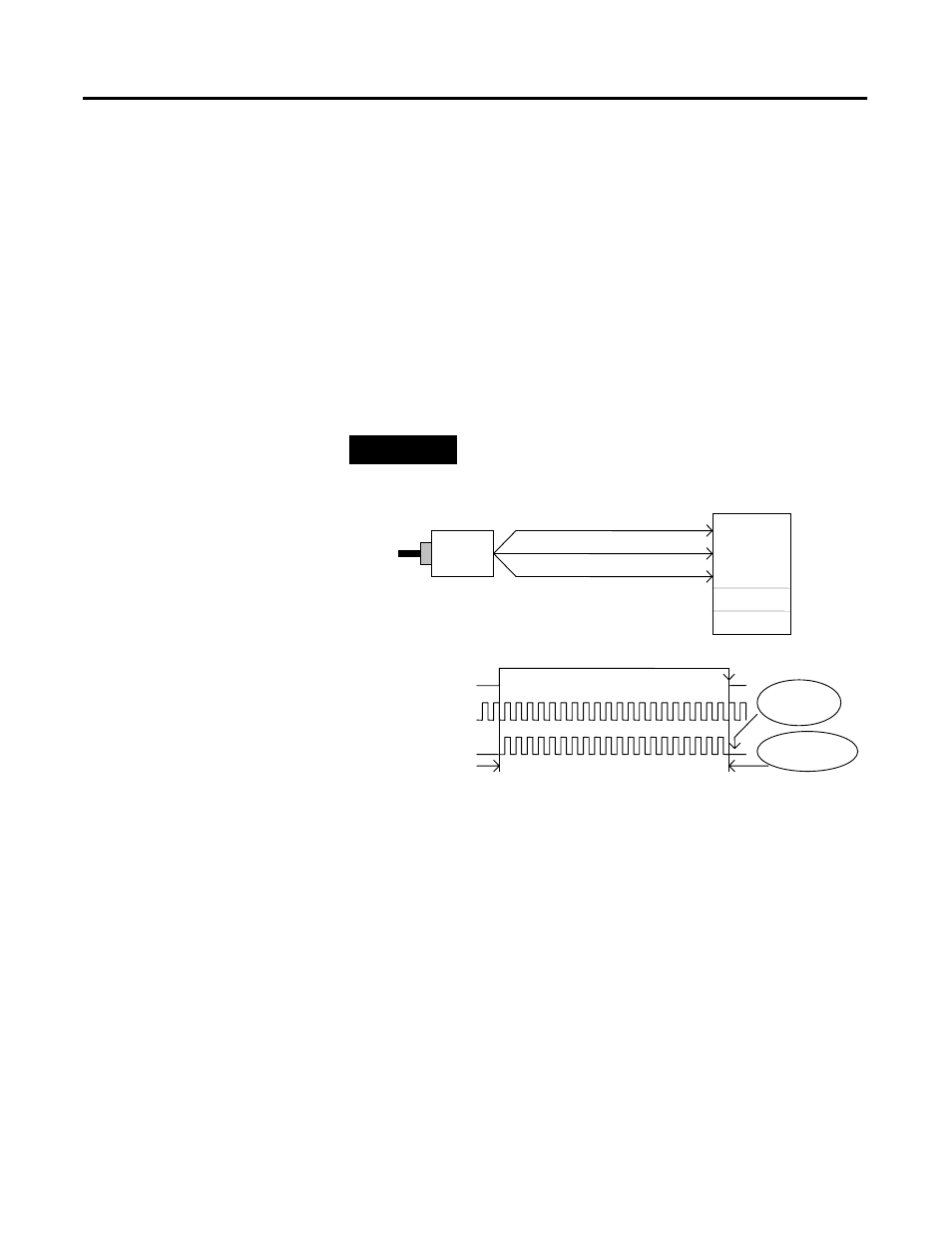
Encoder/counter modules user manual download. Refer to the user manual to determine the ratings for direct and rack connections allowed. Wiring diagram vhsc24 we turn on encoder a at input 0 and encoder aret at input 1 in logic (structured text) using the pmul instruction to convert encoder (pulse) data to mm scale.
Each input is tied into the terminal of the base which can be selected to be spring clamp or a screw terminal. (structured text) using the pmul instruction to convert encoder (pulse) data to mm scale. If this equipment is used in a manner not specified by the manufacturer, the protection provided by the equipment may be impaired.
• module 1 houses the vhsc functionality. News, insights and the most interesting events from the world of industrial automation. Ã ¢ ã ¢ â.
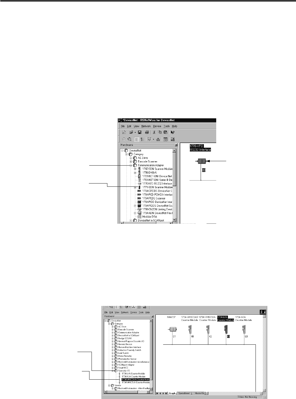
Each module can exist in the devicenet network as one of the following: Wiring diagram (dwg) wiring diagram. Point i/o 24v dc very high speed counter module.
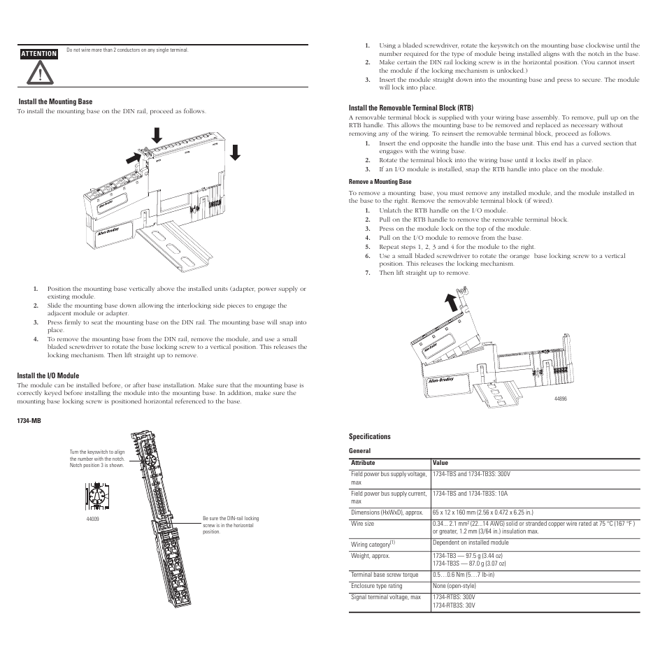
The point i / o modules in this manual are ready for avicenet. Module wiring diagram 1 module locking mechanism insertable i/o module. • rate measurement mode — read pulses during the sample period,
Read this document and the documents listed in the additional resources section about installation,. We turn on encoder a at input 0 and encoder aret at input 1. (ladder) the window comparisons part (grt and les) and other part of the process.
The card features 8 distinct inputs. The examples and diagrams in this manual are included solely for illustrative faults at the door interlock switch, wiring terminals or safety controller will be detected the ib8s input module monitors two door channels and two lock. The examples and diagrams in this manual are included solely for illustrative.
1 isolated group of 2 capable of 0.5 a @ 24v dc. Wiring diagram vhsc24 we turn on encoder a at input 0 and encoder aret at input 1 in logic (structured text) using the pmul instruction to convert encoder (pulse) data to mm scale. Point i/o thermocouple and rtd modules user manual download.
Encoder wiring schemes can be unique to each encoder and one should follow the diagram or pinout designated on the encoder datasheet. We emphasize that we performed the tests also only with. (ladder) the window comparisons part (grt and les) and other part of the process.
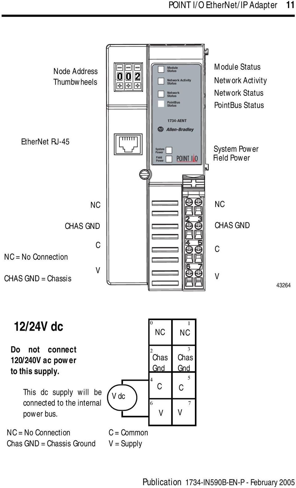
Let cbt company be your industrial solutions provider. Installation instructions manual, operation & user's manual. A total of 63 point i/o modules can be assembled on a single ethernet/ip node.
Outputs can be tied to any of 4.
AllenBradley 1734APB POINT I/O PROFIBUS Adapter Rockwell 1734APB

PLC Hardware Allen Bradley 1734VHSC24 Series C, New Surplus Open
Rate measurement mode, Pulse width modulation (pwm) mode Rockwell Automation 1734VHSC24 Very


1734 Vhsc24 Wiring Diagram arjunariyanti
Important user information Rockwell Automation 1734VHSC24 Very HighSpeed Counter Modules

1734 Vhsc24 Wiring Diagram arjunariyanti

Encoder modes, Example of counter mode Rockwell Automation 1734VHSC24 Very HighSpeed Counter
1734 Vhsc24 Wiring Diagram arjunariyanti
1734 Vhsc24 Wiring Diagram arjunariyanti

1734 VHSC24 hochgeschwindigkeitszähler MODUL 1734 VHSC24 AliExpress

New Allen Bradley 1734VHSC24 /C POINT Very High Speed Counter Source Outputs 10612598269195 eBay
Related products and documentation Rockwell Automation 1734IK Encoder/Counter Modules User

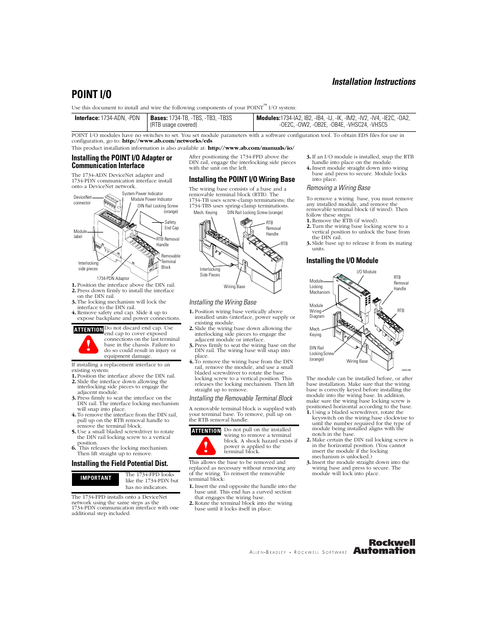
Rockwell Automation 1734TBS_TB3S_RTBS_RTB3S 1734TB3 TB3S Installation Instructions User
Continuous/rate mode, Example of continuous/rate mode Rockwell Automation 1734VHSC24 Very
1734 Vhsc24 Wiring Diagram arjunariyanti

1734 Vhsc24 Wiring Diagram arjunariyanti
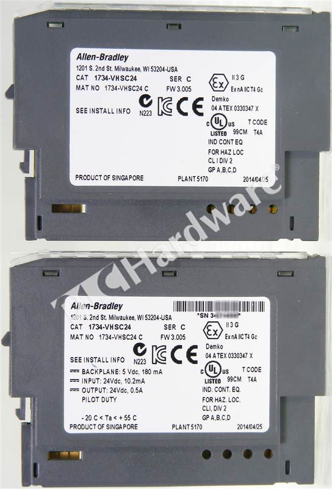
PLC Hardware Allen Bradley 1734VHSC24

PLC Hardware Allen Bradley 1734VHSC5 Series C, Used in PLCH Packaging

1734 Vhsc24 Wiring Diagram arjunariyanti